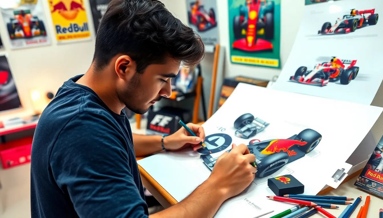
Drawing F1 cars combines the thrill of motorsport with artistic expression, creating stunning visual masterpieces that capture speed and precision on paper. Whether you’re a racing enthusiast or an aspiring artist, mastering F1 car drawings opens up endless creative possibilities.
We’ve all admired the sleek aerodynamic lines and intricate details that make Formula 1 cars engineering marvels. From Lewis Hamilton’s Mercedes to Max Verstappen’s Red Bull, these machines represent the pinnacle of automotive design. Learning to draw them isn’t just about replicating shapes – it’s about understanding proportions, perspective and the technical elements that make each car unique.
Our comprehensive guide will transform your F1 drawing skills from basic sketches to professional-quality artwork. We’ll explore essential techniques, share insider tips and provide step-by-step tutorials that’ll have you creating impressive F1 illustrations in no time.
Getting Started With Basic F1 Car Shapes and Proportions
Understanding the fundamental proportions of Formula 1 cars forms the cornerstone of successful automotive illustration. We’ll explore the essential dimensions and geometric principles that make these racing machines instantly recognizable.
Understanding F1 Car Dimensions
Length measurements define the overall character of modern F1 cars, typically spanning 5.6 to 5.8 meters from nose to rear wing. We measure these proportions using a 3:1 ratio system where the car’s length equals three times its height. The wheelbase accounts for approximately 60% of the total length, creating the distinctive elongated appearance that separates F1 cars from regular vehicles.
Width specifications contribute significantly to the aggressive stance these cars display on track. Current F1 regulations limit car width to 2 meters, including the front and rear wings. We observe that the main body occupies roughly 1.8 meters of this width, while the remaining space accommodates aerodynamic elements like wing endplates and mirrors.
Height proportions create the low-slung profile that makes F1 cars appear to hug the ground. Modern F1 cars measure only 950mm in height, creating a length-to-height ratio of approximately 6:1. We notice this creates the characteristic wedge shape when viewed from the side, with the nose positioned lower than the rear wing.
Essential Drawing Tools for F1 Cars Drawing
Pencil selection impacts the quality and precision of your F1 car illustrations significantly. We recommend using H pencils (2H to 4H) for initial construction lines and geometric shapes, as they produce light marks that won’t interfere with final details. B pencils (2B to 6B) work best for shading cockpit areas, tire treads, and creating depth in aerodynamic components.
Paper choices affect how well your F1 car drawings capture fine technical details and smooth curves. We prefer using medium-weight drawing paper (140-160gsm) with a slight tooth texture for graphite pencil work. Bristol board provides excellent results for detailed technical drawings, while marker paper works well if you plan to add color using alcohol-based markers.
Measurement tools ensure your F1 car proportions remain accurate throughout the drawing process. We use a proportional divider to maintain consistent scale relationships between different car components. A clear plastic ruler helps establish vanishing points for perspective drawings, while a circle template assists in drawing perfect wheels and curved aerodynamic elements.
Basic Geometric Foundation Techniques
Rectangle construction provides the framework for establishing proper F1 car proportions from the start. We begin by drawing a rectangle with a 3:1 length-to-height ratio to represent the car’s basic silhouette. This primary rectangle gets divided into thirds horizontally, with the front third containing the nose cone, the middle third housing the cockpit, and the rear third accommodating the engine cover and rear wing.
Circle placement determines wheel positioning and establishes the car’s stance on the ground. We position two circles within our base rectangle, placing the front wheel at the 25% mark and the rear wheel at the 75% mark along the length. Each wheel circle should have a diameter equal to approximately one-sixth of the car’s total length, maintaining realistic proportions.
Triangle integration helps define the distinctive wedge profile that characterizes modern F1 car aerodynamics. We overlay triangular shapes to establish the nose cone angle, cockpit opening, and rear wing positioning. The nose triangle slopes downward at roughly 15 degrees from horizontal, while the rear wing triangle creates an upward angle of approximately 20 degrees, generating the characteristic rake that improves aerodynamic efficiency.
Mastering the F1 Car Chassis and Body Structure
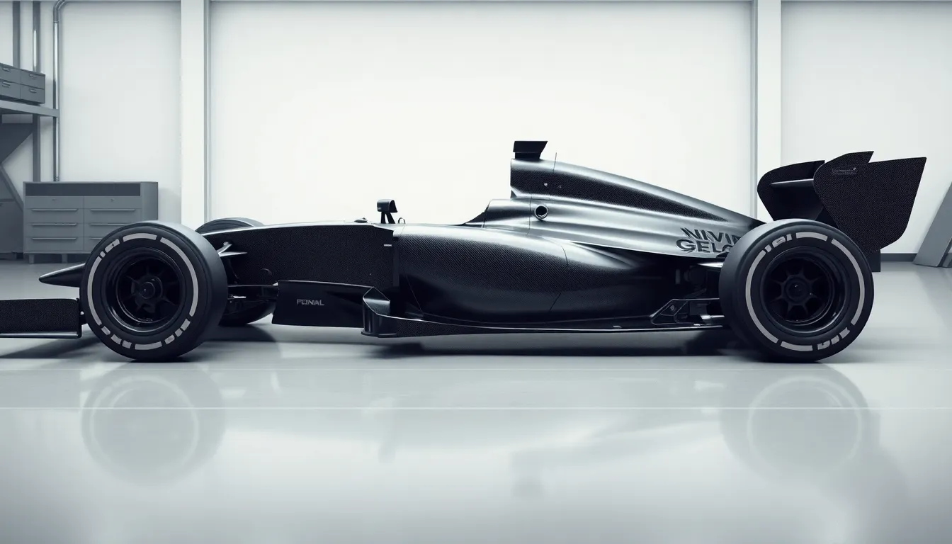
Drawing accurate F1 car body structures requires understanding the complex engineering that defines modern Formula 1 design. We’ll explore the critical components that form the backbone of these incredible racing machines.
Drawing the Monocoque Framework
Monocoque construction serves as the foundation for every F1 car drawing we create. We start by sketching a elongated bathtub shape that extends from the nose to the rear axle line. This carbon fiber survival cell measures approximately 3.5 meters in length and provides the structural integrity for the entire vehicle.
Central positioning determines the accuracy of our monocoque framework. We place the driver’s seating area roughly 60% toward the rear of the total car length. The cockpit opening should appear as a narrow rectangle with rounded corners, measuring about 850mm in length and tapering from 500mm at the front to 400mm at the rear.
Side elevation angles create the distinctive F1 profile we recognize instantly. We draw the monocoque with a gradual upward slope from nose to cockpit, then a steeper decline toward the rear. The highest point sits just behind the driver’s helmet position, creating that characteristic wedge shape essential to proper F1 car proportions.
Creating Accurate Side Pod Shapes
Side pod placement begins with positioning these aerodynamic elements alongside the monocoque structure. We sketch them as teardrop shaped volumes that start narrow at the front suspension area and expand dramatically toward the rear wheels. These pods typically measure 1.2 meters in length and reach their maximum width of 400mm at the midpoint.
Airflow channels define the internal structure of side pods in our drawings. We create distinctive undercuts beneath each pod to show the venturi tunnels that generate ground effect downforce. These concave sections appear as dramatic scoops that extend from the front edge to approximately two thirds of the pod’s total length.
Cooling inlet details add realism to our side pod illustrations. We draw rectangular or kidney shaped openings on the upper surfaces, positioned about 300mm behind the front edge of each pod. These intakes should appear proportionally smaller than the main pod volume, roughly 150mm wide by 100mm tall.
Sketching the Nose Cone Design
Nose cone geometry starts with a elongated cone shape that tapers dramatically from the front wing mounting point to the monocoque junction. We begin with a front width of 1.6 meters at the wing attachment and narrow it to approximately 400mm where it meets the survival cell. The total nose length measures about 1.2 meters in modern F1 regulations.
Profile curvature creates the distinctive S shaped nose profile we see on contemporary Formula 1 cars. We draw the upper surface with a gentle downward slope for the first 600mm, then curve upward to meet the monocoque at cockpit level. This compound curve helps direct airflow over and under the car efficiently.
Mounting pylons connect the nose structure to the front wing assembly in our technical drawings. We sketch these support columns as streamlined vertical elements, typically two per car, positioned symmetrically about 400mm apart. Each pylon should appear roughly 100mm wide and extend 200mm below the nose cone’s lowest point to reach the wing plane.
Capturing the Iconic F1 Wheel and Tire Details
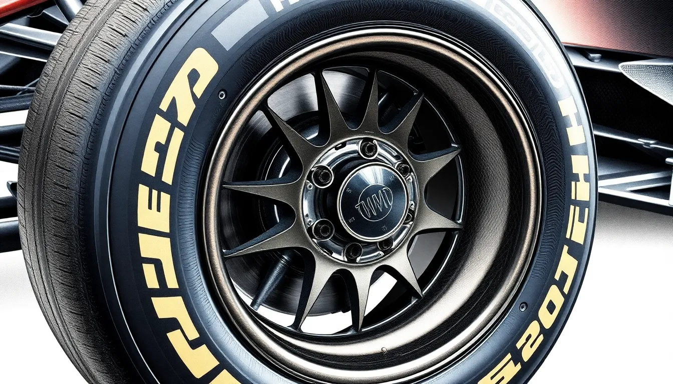
The wheels and tires represent some of the most technically complex components in our F1 car drawings. Understanding these intricate details transforms basic sketches into professional motorsport illustrations.
Drawing Racing Slick Tire Treads
Racing slicks present unique challenges since they feature completely smooth surfaces without traditional tire patterns. We start by establishing the tire’s sidewall profile using gentle curved lines that show the rubber’s natural bulge under load. The contact patch where the tire meets the track requires careful attention to pressure distribution and slight flattening effects.
Temperature variations create subtle surface textures that we can represent through light shading techniques. Hot slicks develop a glossy appearance that we capture using strategic highlight placement along the tire’s crown. The sidewall markings include exact Pirelli branding and compound indicators that add authenticity to our drawings.
Wear patterns become visible during race conditions and create distinctive surface characteristics. We illustrate these effects through graduated shading that shows heat buildup and rubber grain development. The tire’s edge where it meets the rim demands precise line work to show the mounting bead and sidewall transition.
Sketching Wheel Rim Specifications
Modern F1 wheel rims measure exactly 330mm in diameter and feature complex spoke patterns designed for optimal airflow. We begin our rim drawings by establishing the central hub area where the wheel nut and retention system connect. The spoke configuration varies between teams but typically includes five primary supports that we draw using precise angular measurements.
Brake cooling requirements dictate rim design with exact ventilation channels that we must accurately represent. These cooling vents appear as deliberate gaps between spokes and require careful perspective work to show depth and airflow direction. The rim’s outer lip features a distinctive profile that creates the tire mounting surface.
Weight reduction holes appear throughout modern F1 rims and create interesting shadow patterns in our drawings. We sketch these openings using consistent sizing and spacing to maintain the wheel’s structural integrity appearance. The rim’s finish typically shows a matte carbon fiber texture that we render through subtle crosshatching techniques.
Adding Brake Disc Components
F1 brake discs measure 330mm in diameter and feature distinctive cooling vane patterns that create dramatic visual elements. We start by drawing the disc’s outer edge with its characteristic scalloped profile designed to reduce weight and improve heat dissipation. The cooling vanes between the disc faces require precise radial line work to show their angled orientation.
Carbon brake discs display unique surface textures that develop through extreme heat cycles. We represent this weathered appearance using varied pencil pressure to create subtle grain patterns and heat checking effects. The disc mounting points where it connects to the wheel hub need accurate bolt circle positioning.
Brake caliper components peek through the wheel spokes and add mechanical complexity to our drawings. These bright colored elements typically appear in team exact colors like Ferrari red or McLaren orange. The caliper housing requires careful shading to show its three dimensional form and cooling fin details.
Brake pad wear indicators and dust shields provide additional technical details that enhance realism. We sketch these components using sharp clean lines to contrast with the curved brake disc surfaces. The entire brake assembly creates dramatic shadows within the wheel well that we capture through graduated shading techniques.
Perfecting the F1 Engine and Air Intake Systems
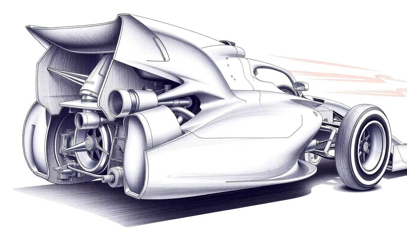
Drawing F1 engine components and air intake systems requires understanding the complex aerodynamics that power these incredible machines. We’ll explore the technical details that transform basic sketches into accurate representations of modern Formula 1 powertrains.
Drawing Air Box and Intake Openings
Air box positioning sits directly behind the driver’s helmet and serves as the primary breathing apparatus for F1 engines. We start by sketching a rectangular opening that measures approximately 200mm wide by 100mm tall, positioned at the car’s highest point for optimal airflow capture.
Intake channel geometry features smooth curved walls that funnel air downward toward the engine bay. We draw these channels with gentle S-curves that avoid sharp angles, ensuring proper airflow visualization in our illustrations.
Opening dimensions vary between teams but typically maintain consistent proportions across the grid. We sketch the main intake with a 3:2 width-to-height ratio, creating the characteristic rectangular shape that defines modern F1 air boxes.
Secondary intakes appear as smaller openings along the engine cover sides, measuring roughly 50mm in diameter. We position these circular vents strategically to show the cooling requirements for various engine components.
Airflow indicators can be represented through subtle shading techniques that suggest air movement patterns. We use light pencil strokes radiating from intake openings to demonstrate the powerful suction these systems create during high-speed operation.
Sketching Engine Cover Lines
Engine cover profile follows the car’s aerodynamic requirements while housing complex mechanical components beneath. We begin with a smooth curved line that rises from the cockpit area and slopes downward toward the rear wing mounting points.
Centerline definition runs straight down the middle of the engine cover, creating a subtle ridge that helps with aerodynamic stability. We draw this line as a gentle raised section that’s barely visible but adds structural realism to our illustrations.
Side panel curvature flows outward from the centerline to accommodate the engine’s width requirements. We sketch these curves with smooth arcs that maintain consistent proportions throughout the cover’s length.
Cooling louvers appear as small rectangular openings that release hot air from the engine bay. We draw these as precise geometric shapes, typically measuring 10mm by 30mm, arranged in strategic patterns along the cover’s surface.
Panel separation lines indicate where different cover sections meet during assembly. We represent these joints with thin lines that follow the car’s natural contours, adding technical authenticity to our F1 engine drawings.
Creating Exhaust Pipe Details
Exhaust exit positioning places the tailpipe opening directly above the rear crash structure in modern F1 regulations. We sketch a circular opening measuring approximately 100mm in diameter, centered between the rear wing pylons.
Pipe curvature shows the complex routing required to meet regulatory specifications while optimizing performance. We draw smooth bends that curve upward from the engine bay, avoiding sharp angles that could restrict exhaust flow.
Heat shield details surround the exhaust system to protect nearby components from extreme temperatures. We add rectangular panels with ventilation slots, positioned strategically around the pipe’s path through the engine bay.
Mounting brackets secure the exhaust system to the car’s structure and appear as small triangular supports. We sketch these elements as precise geometric shapes that connect the pipe to the main chassis framework.
Temperature indicators can be suggested through subtle color variations or shading techniques. We use graduated tones around exhaust components to show the heat distribution patterns that develop during operation, adding realistic depth to our F1 powerplant illustrations.
Adding Advanced Aerodynamic Elements to Your F1 Drawing
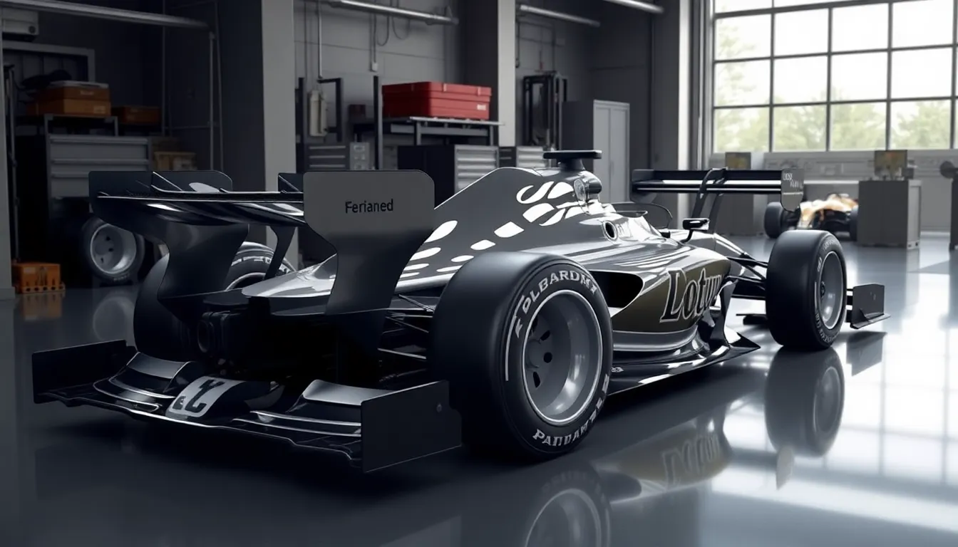
We’ll now focus on the sophisticated aerodynamic elements that define modern Formula 1 cars and separate amateur sketches from professional automotive artwork.
Drawing Front Wing Components
Front wings serve as the most complex aerodynamic element in F1 car drawings, featuring multiple flap configurations and endplate designs. We start by establishing the main plane structure, which typically spans 1.8 meters in width and sits approximately 50-75mm above the ground clearance line.
Flap elements require precise angular positioning, with the top flap angled between 15-25 degrees relative to the main plane. We draw these secondary elements using parallel construction lines to maintain consistent spacing of roughly 10-15mm between each flap layer. Upper flaps connect to the main wing through small support pillars that we represent as thin vertical rectangles.
Endplates demand careful attention to their curved profiles and regulatory slots. We sketch the outer endplate edge as a gentle S-curve that extends from the nose cone attachment point down to the ground effect zone. Mandated slot openings appear as small rectangular cutouts positioned in the lower third of each endplate structure.
Wing support pillars connect the entire assembly to the nose cone through precisely positioned mounting points. We draw these connection elements as tapered cylinders that narrow from 15mm diameter at the nose attachment to 8mm at the wing junction. Adjustment mechanisms appear as small circular elements where the wing meets each support structure.
Sketching Rear Wing Structures
Rear wing assemblies create the primary downforce balance for F1 cars and require understanding of their dual element design principles. We establish the main wing plane first, measuring approximately 950mm in width and positioned 800-950mm above the rear axle centerline.
Main wing elements feature aggressive angle settings typically ranging from 25-35 degrees depending on track requirements. We draw the primary wing surface using a gentle arc that creates maximum chord length at the center section, tapering toward the endplates. Secondary flap elements sit above the main plane with 20-30mm separation gaps.
Endplate construction follows strict regulatory dimensions with vertical surfaces extending 200mm above the main wing chord line. We sketch these vertical elements as precise rectangles with small radius corners at their intersection points. Connection bridges link the main wing to the upper flap through streamlined support brackets.
Wing adjustment mechanisms appear as small actuator housings positioned within the endplate structures. We represent these components as cylindrical elements roughly 25mm in diameter with visible mounting flanges. Support pylons extend from the rear crash structure to the wing assembly through carefully positioned attachment points.
Creating DRS System Details
DRS systems transform rear wing performance through moveable upper flap mechanisms that we must accurately represent in technical drawings. We begin by sketching the fixed main wing element exactly as described in standard rear wing construction techniques.
Moveable flap assemblies require precise hinge mechanism representation along the rear edge of the main wing element. We draw these pivot points as small circular elements spaced approximately 150-200mm apart across the wing span. Actuator housings appear as rectangular boxes measuring roughly 40mm x 30mm positioned within the left endplate structure.
Gap dimensions between the main wing and DRS flap measure 50-85mm when the system activates during qualifying and race conditions. We illustrate this opening as a clean separation line that runs parallel to both wing elements. Connection rods link the actuator mechanism to the moveable flap through precisely positioned attachment brackets.
Electrical connections route through the endplate structure to power the DRS actuator system during permitted track zones. We represent these components as thin line elements running from the wing assembly toward the main chassis electrical systems. Safety backup mechanisms appear as secondary spring loaded elements within the actuator housing structure.
Incorporating Sponsor Logos and Racing Numbers
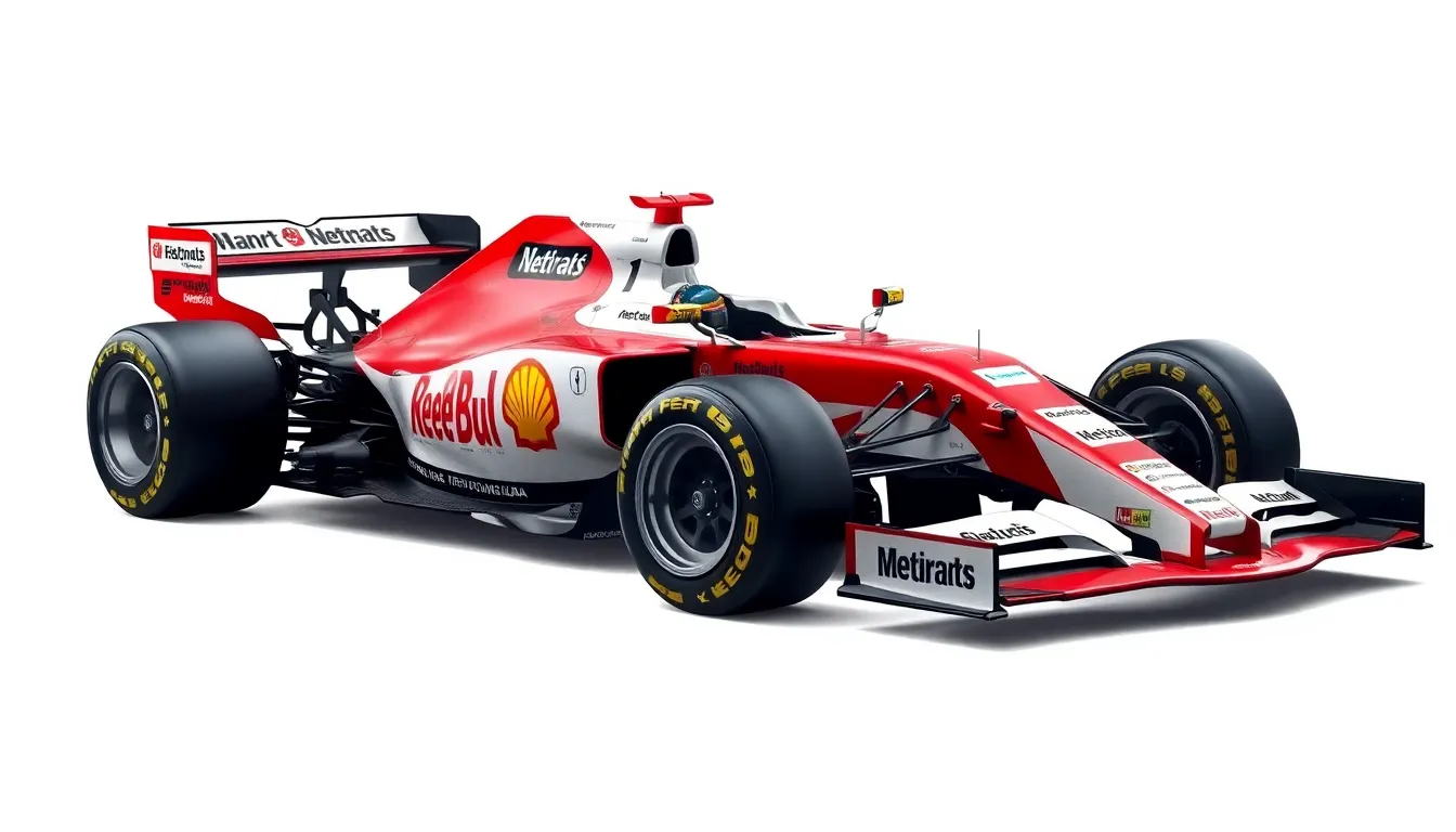
Sponsor branding and racing numbers transform technical F1 car drawings into authentic representations of exact teams and drivers. These visual elements require careful placement and proportion to maintain the drawing’s accuracy while showcasing the commercial partnerships that fuel Formula 1.
Positioning Team Sponsor Decals
Primary sponsor locations dominate the front nose cone and engine cover areas where television cameras capture maximum exposure. We position the main title sponsor logo across the engine cover’s central section, typically measuring 800mm to 1200mm in width depending on the car’s proportions. The nose cone receives secondary treatment with smaller sponsor decals ranging from 200mm to 400mm in height.
Side pod surfaces provide premium real estate for multiple sponsor brands arranged in hierarchical order based on partnership value. Major sponsors occupy the forward sections near the cockpit opening while supporting brands fill the rear portions toward the engine cover transition. We maintain consistent spacing of approximately 50mm between individual decals to prevent visual clustering.
Wing element branding requires precise scaling to match the component’s dimensions without overwhelming the aerodynamic structure. Front wing endplates accommodate vertical sponsor strips measuring 150mm in height while rear wing elements display horizontal branding across their 950mm maximum width. The DRS flap often features contrasting sponsor colors that become visible during activation.
Wheel cover decorations present unique circular challenges requiring curved text adaptation and radial logo placement. We position primary sponsors at the wheel’s center hub while secondary brands follow the rim’s circumference at exact intervals. Modern F1 regulations limit wheel cover branding to 300mm diameter circles to maintain safety visibility requirements.
Drawing Racing Number Styles
Contemporary number fonts follow strict FIA regulations requiring 250mm minimum height on side panels and 200mm height on nose sections. We draw these numbers using bold, sans serif typefaces with stroke widths measuring 25mm to ensure television broadcast clarity. The official F1 font features rounded corners and consistent character spacing of 50mm between digits for double digit numbers.
Color contrast requirements mandate exact combinations to maximize visibility against varying car liveries and track conditions. Numbers appear in white on dark backgrounds or black on light surfaces with contrasting outline treatments measuring 5mm in width. We apply yellow highlighting for championship leaders and special event recognition following FIA sporting regulations.
Background panels provide essential contrast zones measuring 400mm in width and 300mm in height to frame the racing numbers effectively. These panels feature rounded corners with 25mm radius curves and maintain 25mm margins around the number’s perimeter. Team colors or sponsor coordination influence panel selection while preserving regulatory compliance.
Number placement zones occupy designated areas on the nose cone center, cockpit sides, and engine cover rear section. We position nose numbers 150mm behind the front wing mounting points while side numbers align with the cockpit opening’s centerline. Engine cover numbers sit 200mm forward of the rear wing mounting structures to avoid aerodynamic interference.
Adding Driver Helmet Visibility
Helmet positioning within the cockpit opening requires accurate head restraint and halo integration to achieve realistic proportions. We draw the helmet’s crown 50mm below the halo’s central section while maintaining 75mm clearance on either side. The helmet’s face opening aligns with the cockpit’s forward edge to simulate proper driver visibility angles.
Visor reflection techniques capture the curved surface properties using graduated shading from light to dark across the helmet’s face shield. We apply highlight strips along the visor’s upper edge measuring 5mm in width while darker regions occupy the lower sections. These reflections often mirror track elements or sky conditions visible from the driver’s perspective.
Helmet design details showcase individual driver personalities through custom paint schemes and sponsor integration. We incorporate team colors as base layers while adding personal elements like national flags, career achievements, or family tributes. Modern helmets feature matte finish sections contrasting with gloss areas to create visual depth and texture variation.
Safety equipment visibility includes the HANS device’s carbon fiber straps extending from helmet to shoulder harness attachment points. We draw these straps as 50mm wide elements positioned at 45 degree angles from the helmet’s base. Additional details include the helmet’s drinking tube connection and radio communication antenna extending 25mm above the helmet’s rear section.
Shading and Finishing Techniques for Realistic F1 Cars Drawing
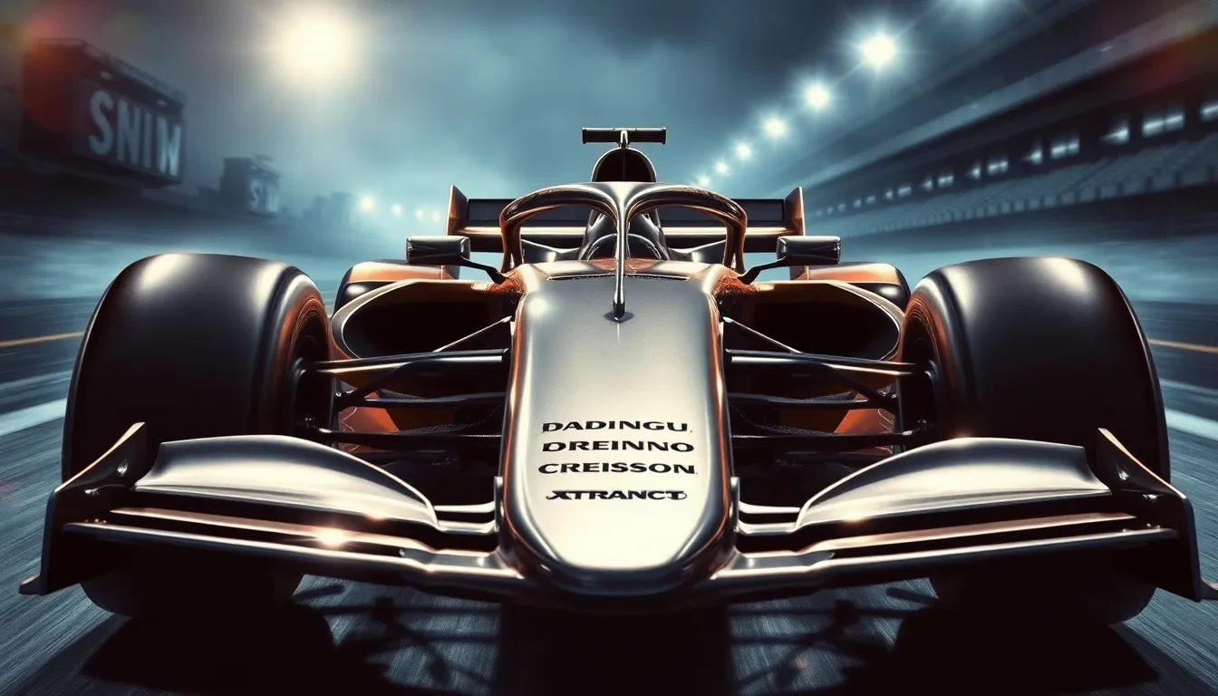
Mastering professional shading transforms your technical F1 sketches into stunning photorealistic artwork. We’ll explore advanced techniques that capture the sophisticated surface materials and lighting effects that define modern Formula 1 cars.
Creating Metallic Surface Effects
Metallic surfaces require precise highlight and shadow placement to achieve convincing reflections. Start with medium-toned base shading using 2H and HB pencils across the entire metallic component. Build darker shadow areas with 2B pencils in recessed sections like suspension mounting points and chassis joints.
Create sharp highlight streaks along the edges of suspension arms and wing supports using a kneaded eraser. These highlights should follow the natural curve of each component, typically running parallel to the car’s centerline. Position your primary highlight approximately one-third from the top edge of each metallic surface.
Add reflected environment details by incorporating subtle dark bands that suggest surrounding objects. Use light vertical strokes with a 4H pencil to represent reflections of track barriers or pit equipment. These environmental reflections typically appear as soft horizontal bands across larger metallic surfaces like brake discs and suspension components.
Polish the metallic finish with careful blending using a tortillon or blending stump. Work in circular motions for curved surfaces and linear strokes for straight edges. The key lies in maintaining sharp contrast between highlights and shadows while keeping mid-tones smooth and gradual.
Adding Carbon Fiber Textures
Carbon fiber patterns demand systematic approach to recreate their distinctive woven appearance. Begin by establishing the base tone using consistent 2B pencil strokes across the entire carbon fiber surface. Modern F1 cars feature carbon fiber on nose cones, side pods, and rear wing assemblies.
Draw the weave pattern using precise crosshatching techniques with sharp 4H and 2H pencils. Create small rectangular cells approximately 2mm square when drawing at 1:24 scale. Each cell should contain diagonal lines running in alternating directions to simulate the actual carbon fiber weave structure.
Build texture depth by varying the pressure within each woven cell. Some cells appear slightly darker due to the fiber orientation catching light differently. Use an HB pencil to darken approximately 30% of the cells in a random pattern, avoiding obvious repetitive sequences.
Enhance realism with selective highlighting using a fine eraser or white pencil. Carbon fiber surfaces reflect light in subtle ways, creating small bright spots where the resin coating catches illumination. Add these highlights sparingly, focusing on edges and raised areas where natural light would strike first.
Applying Racing Light Reflections
Racing light effects create ever-changing energy in your F1 car drawings through strategic highlight placement. Position primary light sources to simulate track lighting or sunlight hitting the car from a 45-degree angle above and slightly forward of the vehicle.
Establish strong directional shadows using 3B and 4B pencils on surfaces facing away from your chosen light source. The underside of the front wing, lower side pod sections, and areas beneath the rear wing should receive deeper shadow treatment. These shadows should gradually fade rather than ending abruptly.
Add secondary light bounces that occur naturally in racing environments. Track surfaces reflect important light upward onto the car’s underside, creating subtle illumination in normally shadowed areas. Use 2H pencils to add gentle lighting to the bottom edges of side pods and the lower front wing elements.
Create surface material variations in how they reflect light differently. Painted surfaces produce softer reflections compared to bare carbon fiber or polished metal components. Painted areas like the car’s livery should show broader, more diffused highlights, while metal brake components display sharp, mirror-like reflections.
Finish with atmospheric effects by adding subtle haze or motion blur around the car’s edges. Use a soft 6B pencil to create gentle shadow gradients that suggest speed and movement. These atmospheric touches help separate your F1 car from the background while adding professional polish to the overall composition.
Digital vs Traditional Methods for F1 Cars Drawing
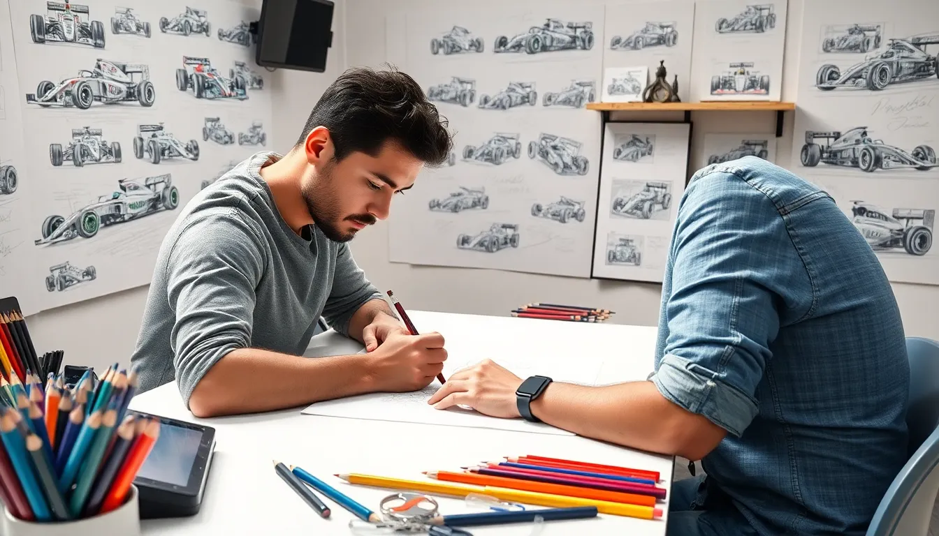
Modern artists face an exciting choice between digital precision and traditional craftsmanship when creating F1 car illustrations. Each approach offers unique advantages that can transform your motorsport artwork from amateur sketches to professional quality pieces.
Best Software for Digital F1 Art
Adobe Photoshop leads the digital art revolution for F1 car drawings with its advanced brush engines and layer blending modes. We’ve found that Photoshop’s custom brush settings perfectly replicate carbon fiber textures and metallic paint finishes that define modern Formula 1 aesthetics. The software’s transformation tools allow precise perspective adjustments essential for capturing aerodynamic profiles.
Procreate dominates tablet based F1 illustration with its intuitive gesture controls and pressure sensitive stylus support. Artists can quickly sketch initial chassis proportions using Procreate’s symmetry guides while maintaining the natural drawing feel that traditional methods provide. The app’s time lapse recording feature helps us analyze our drawing process and identify areas for improvement.
Clip Studio Paint excels at technical line work required for detailed F1 components like brake disc cooling vanes and suspension elements. Its vector layer capabilities ensure clean edges on sponsor logos and racing numbers while maintaining scalability for different print sizes. We particularly appreciate the software’s 3D reference models that help establish accurate wheel positioning and chassis angles.
Adobe Illustrator serves specialized needs for creating precise sponsor decals and technical diagrams within F1 car illustrations. Vector based workflows preserve quality when scaling artwork from business cards to billboard presentations. The pen tool’s bezier curve controls perfectly match the smooth flowing lines found in modern aerodynamic designs.
Traditional Pencil and Paper Techniques
Graphite pencil sets ranging from 9H to 9B provide the tonal range necessary for capturing F1 car surface variations. We recommend starting with 2H pencils for initial proportion guidelines then progressing to 2B and 4B grades for deeper shadows around side pods and brake calipers. Hard pencils maintain crisp edges essential for technical elements while soft grades create smooth gradations on curved surfaces.
Bristol board paper offers the ideal surface texture for detailed F1 car drawings with its smooth finish and substantial weight. The paper’s tooth structure holds graphite layers effectively while allowing precise eraser work for highlight creation on metallic components. We prefer 300 series bristol board that withstands multiple rendering sessions without surface deterioration.
Blending stumps and tortillons create the seamless surface transitions that distinguish professional F1 car artwork. These tools excel at rendering the subtle shadow gradations found between aerodynamic elements and chassis components. Chamois cloth works particularly well for large area blending on engine covers and side pod surfaces.
Kneaded erasers provide essential highlight recovery capabilities for depicting glossy paint surfaces and chrome exhaust pipes. Unlike standard erasers, kneaded varieties can be shaped into fine points for precise light reflection details on brake discs and suspension components. We use them extensively for creating rim spoke highlights and sponsor logo contrast effects.
Combining Both Approaches
Hybrid workflows maximize the strengths of traditional sketching with digital refinement capabilities. We typically begin F1 car drawings with pencil sketches to establish natural proportions and gesture then scan artwork at 600 DPI resolution for digital enhancement. This approach preserves the organic quality of hand drawn lines while gaining access to digital color palettes and texture libraries.
Digital color overlays transform monochrome pencil drawings into vibrant team exact illustrations. Scanning traditional line work allows us to add authentic sponsor colors, racing stripe patterns, and environmental reflections while maintaining the drawing’s original character. Multiply and overlay blending modes preserve underlying pencil textures that digital brushes struggle to replicate naturally.
Traditional detail passes over digital foundations combine precision with artistic expression. We often create basic F1 car structures digitally for accurate proportions then print blue line guides for traditional rendering work. This method ensures technical accuracy in chassis dimensions while allowing expressive shading techniques that bring personality to each illustration.
Reference photo integration bridges both mediums through careful observation and selective digital enhancement. Traditional sketching from F1 race photography develops observational skills while digital tools help analyze complex lighting conditions and surface materials. We photograph our traditional sketches under various lighting conditions to understand how digital color theory applies to pencil rendered forms.
Common Mistakes to Avoid in F1 Cars Drawing
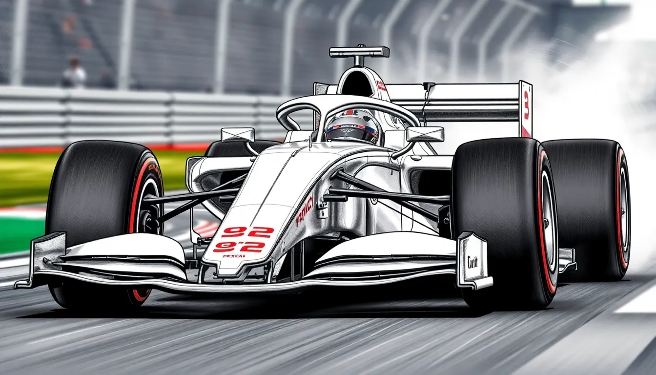
Drawing Formula 1 cars presents unique challenges that can trap even experienced artists in common pitfalls. We’ve identified the most frequent errors that prevent drawings from achieving professional quality and realism.
Proportion Errors in Car Dimensions
Wheelbase miscalculations represent the most critical proportion error in F1 car drawings. We often see artists compress the 3.3 to 3.7 meter wheelbase distance, making cars appear toy-like rather than the imposing machines they are. The distance between front and rear axles should occupy roughly 60% of the total car length in side view drawings.
Height compression creates another frequent proportion mistake. Modern F1 cars measure only 950mm in height, yet many artists draw them too tall relative to their 2-meter width. We recommend using the wheel diameter as a measuring unit since F1 wheels are 330mm in diameter, meaning the car height equals approximately 2.9 wheel diameters.
Cockpit opening size often appears oversized in amateur drawings. The actual cockpit opening measures approximately 850mm in length, which should appear proportionally smaller against the car’s 5.6 to 5.8 meter total length. We suggest sketching the driver’s helmet first to establish correct cockpit proportions.
Front wing width errors commonly occur when artists make wings appear narrower than the car body. The front wing spans the full 2-meter car width and extends slightly beyond the front wheels. Drawing the wing too narrow destroys the car’s aggressive stance and aerodynamic appearance.
Overlooking Aerodynamic Accuracy
Simplified wing elements fail to capture the sophisticated aerodynamics that define modern F1 cars. We see drawings with basic flat wing surfaces instead of the complex multi-element configurations with precise angle relationships. Front wings feature five separate flap elements, each angled differently to manipulate airflow layers.
Missing endplate complexity reduces wing realism significantly. F1 wing endplates contain intricate cutouts, vanes, and curved surfaces designed for vortex generation. We recommend studying reference photos to understand these technical details rather than drawing simple flat endplates.
Bargeboards and floor edges require careful attention to aerodynamic flow patterns. These elements feature complex curved surfaces and sharp edges that channel airflow around the car. Drawing them as simple geometric shapes ignores their sophisticated engineering purpose and visual impact.
DRS flap positioning often appears incorrect in static drawings. The Drag Reduction System flap should align perfectly with the main wing element when closed, creating a seamless surface. We notice many artists draw gaps or misaligned angles that wouldn’t function in real racing conditions.
Incorrect Perspective Issues
Vanishing point confusion creates the most obvious perspective errors in F1 car drawings. We recommend establishing clear horizon lines and vanishing points before starting detailed work. Single-point perspective works best for head-on views, while two-point perspective suits ever-changing three-quarter angles.
Wheel ellipse distortion reveals perspective mistakes immediately. Wheels appear as perfect circles only in direct side view, transforming into ellipses from all other angles. We suggest practicing wheel ellipses separately to master their changing proportions at different viewpoints.
Foreshortening inconsistencies occur when different car elements follow conflicting perspective rules within the same drawing. The nose cone, cockpit, and rear wing must all conform to the same vanishing points and perspective system. Drawing guidelines and construction lines help maintain consistency throughout the illustration.
Ground plane integration frequently appears disconnected from the car itself. F1 cars sit extremely low to the ground with minimal clearance, yet many drawings show them floating above the surface. We emphasize drawing the contact patches where tires meet the track to establish proper ground plane relationships.
Conclusion
Drawing Formula 1 cars successfully combines technical precision with artistic expression. We’ve covered everything from basic proportions and geometric foundations to advanced shading techniques and aerodynamic details that bring these incredible machines to life on paper.
The journey from simple sketches to professional-quality illustrations requires patience and practice. By mastering the fundamental shapes avoiding common mistakes and understanding the engineering behind these racing marvels you’ll develop the skills needed to create stunning F1 artwork.
Remember that every professional artist started with basic shapes and gradually built their expertise. Whether you’re capturing Lewis Hamilton’s Mercedes or Max Verstappen’s Red Bull the techniques we’ve shared will help you create drawings that truly celebrate the beauty and complexity of Formula 1 racing.
Frequently Asked Questions
What are the standard dimensions of a Formula 1 car?
Modern Formula 1 cars typically measure between 5.6 to 5.8 meters in length, with a maximum width of 2 meters and a height of only 950mm. These specific dimensions are crucial for accurate proportions when drawing F1 cars and are regulated by the FIA to ensure fair competition across all teams.
What basic tools do I need to start drawing F1 cars?
Essential tools include various pencil types (ranging from 2H for light construction lines to 6B for deep shadows), quality drawing paper, measurement tools like rulers and proportional dividers, and erasers for corrections. Having the right tools ensures you can achieve the precision needed for technical F1 illustrations.
How do I establish proper proportions when drawing an F1 car?
Start with basic geometric shapes: use rectangles to establish overall proportions, circles for wheel positioning, and triangles to define the aerodynamic profile. The wheelbase (distance between front and rear axles) serves as your primary measurement reference for scaling all other components accurately.
What are the most common mistakes to avoid when drawing F1 cars?
Critical errors include miscalculating wheelbase dimensions, incorrect height compression, inaccurate cockpit opening sizes, and wrong front wing proportions. Perspective issues like vanishing point confusion and wheel ellipse distortion are also common. Focus on understanding the technical specifications and maintaining consistent proportional relationships throughout your drawing.
How can I make my F1 car drawings look more realistic?
Master advanced shading techniques to capture metallic surfaces, carbon fiber textures, and racing light reflections. Pay attention to sponsor logo placement, racing number styles, and aerodynamic details like wing elements and bargeboard configurations. Environmental reflections and atmospheric effects suggesting speed and movement add professional quality to your illustrations.
What should I focus on when drawing F1 wheels and tires?
Concentrate on the smooth surface of racing slick tires, accurate sidewall profiles, and contact patch representation. Modern F1 wheels are 13 inches in diameter with specific spoke patterns and brake cooling requirements. Include brake disc cooling vane patterns and caliper details to enhance realism and technical accuracy.
How important are aerodynamic elements in F1 car drawings?
Aerodynamic components are crucial for distinguishing professional artwork from amateur sketches. Master the complex flap configurations of front wings, dual-element rear wing structures, and DRS system mechanics. These elements define modern F1 cars and require precise angular positioning and spacing for authentic representation.

